
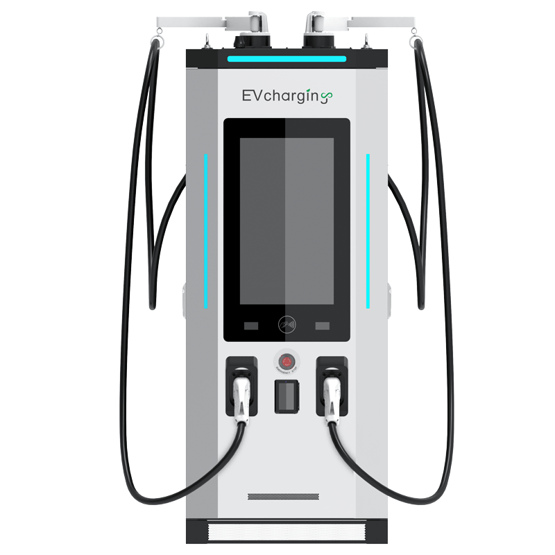
Introduction: Turning Heat From a Headache Into Headroom
Fast DC charging lives or dies by thermal headroom. A liquid cooling module changes that headroom into a steady, predictable envelope for silicon and copper. Picture a fleet hub at dusk, vans queuing, ambient at 38°C, and a site trying to push stable current into every battery without noise or derating. Field data shows that when airflow stalls, fans surge, and thermal throttling hits, throughput drops and session time balloons. But when the coolant loop controls junction temp within a tight band, power converters hold their setpoint and uptime climbs (simple, but critical). So, can we scale to 1000V, keep the rack compact, and still protect devices and power stages under peak stress? And can we do it without turning the enclosure into a wind tunnel? Let’s map the constraints, then open the hood.
Part 2: Under the Hood—Where Air Meets Its Limits
Why do air-cooled stacks struggle?
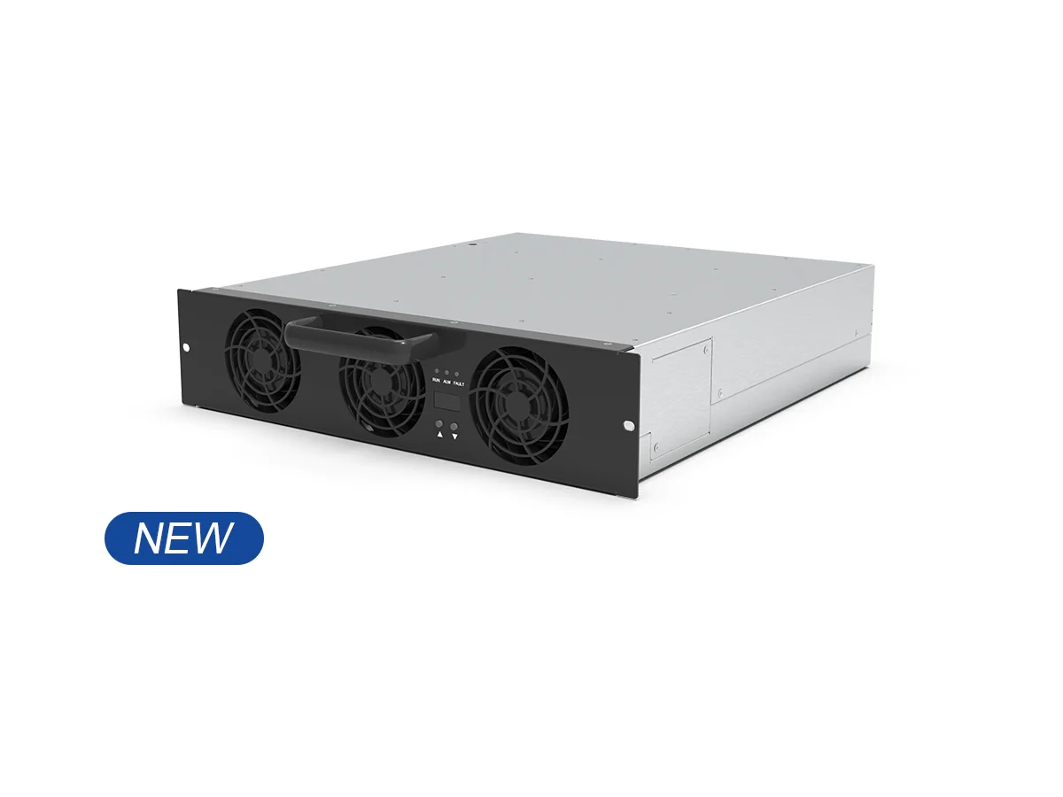
Here’s the direct view: fan walls fight physics at 1000V and high current density. The 40kw EV DC charger module points to a different path, because coolant removes heat at the source, not after it soaks the chassis. Air systems create uneven hotspots across the DC bus and SiC MOSFETs. That forces derate margin, wider guard bands, and higher acoustic load. With liquid, the cold plate spreads heat right where junction-to-case delta is worst. Look, it’s simpler than you think: shorter thermal stack-up equals tighter control loop, which equals stable current delivery.
Traditional racks also hide a subtle penalty—recirculation. As filters clog, airflow drops and the PID hunts to hold setpoint. The result? More switching loss, more stress on IGBTs or SiC dies, and more service calls. Liquid loops with a tuned coolant manifold keep flow laminar and predictable across modules, so the firmware doesn’t chase noise. That means cleaner waveforms, fewer trips, and better MTBF under dirty, high-dust sites. When ambient spikes, air systems chase it; liquid systems buffer it—funny how that works, right?
Part 3: From Coolant to Code—Principles Driving the Next Wave
What’s Next

The next step isn’t just colder hardware; it’s smarter heat paths. A liquid cold plate matched to die layout cuts thermal resistance where it matters, and a right-sized pump curve avoids cavitation while keeping delta-T tight. Pair that with edge computing nodes that watch flow, inlet temp, and device junctions in real time. The result is a control loop that biases coolant flow to the hottest slice of the stack before derating triggers. That’s how a 1000V charging module holds output current steady through peak noon heat or cold-start mornings—without oversizing the whole cabinet. Add predictive analytics on the coolant loop and seals, and you can schedule service before a leak sensor ever chirps (less drama, more uptime).
Zooming out, the comparative picture is clear: air relies on volume; liquid relies on precision. We moved from fan curves to flow maps, from static guards to adaptive setpoints. Summing it up, the gains show up as stable output, quieter sites, and cleaner efficiency at partial load. If you’re evaluating options, focus on three signals that cut through the noise: 1) end-to-end thermal resistance from junction to coolant (K/W) at full load; 2) coolant delta-T and flow stability under transient steps; 3) efficiency and derate behavior across 20–80% duty with real-world dust and vibration. Choose the design that treats heat like data—measured, routed, and resolved—and your field results will follow. For a grounded benchmark in this space, see winline technology.