
Quick read: why RTE wins or loses in a layout
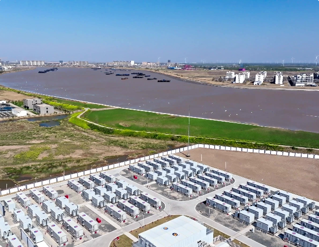
Round-trip efficiency (RTE) is the money-and-power meter on a battery plant. When you sketch a utility-scale layout, small choices add up: transformer sizing, inverter topology, wiring runs, and the battery management system affect how much stored energy actually returns to the grid. For a practical look at manufacturers and real-build approaches, see energy storage battery companies that publish plant specs. Real-world projects — like the Hornsdale Power Reserve in South Australia — show how high RTE (often in the mid-80s for modern lithium-ion at short durations) can make the build pay off in grid services and frequency response.
Layout types and the efficiency trade-offs
There are a few common layouts: centralized inverters with large step-up transformers, distributed inverters in each container, and hybrid setups with DC-DC converters feeding a single AC inverter. Each has pros and cons for RTE.
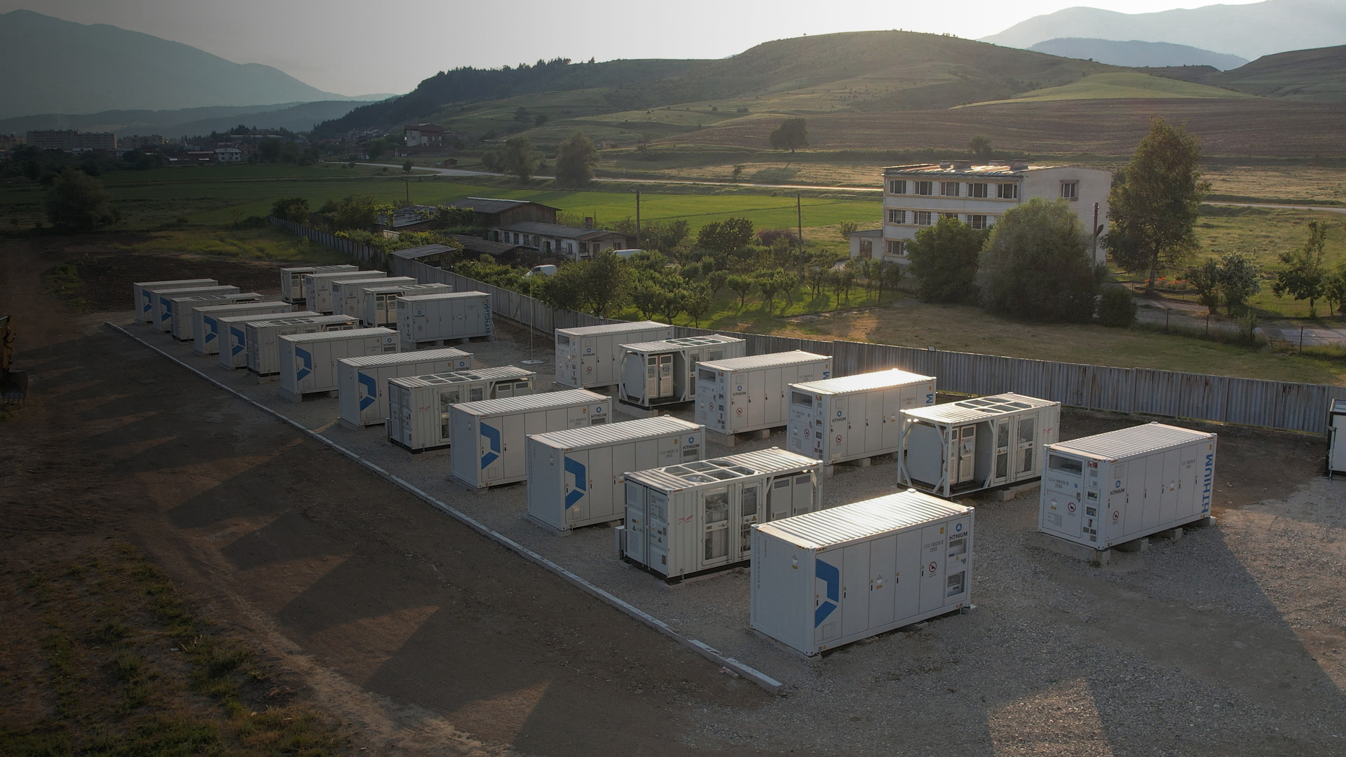
Centralized inverter layouts cut hardware redundancy and are easy to service, but long DC cable runs and extra conversion steps (DC-AC then AC-AC for step-up) add losses. Distributed inverter layouts trim conversion hops and limit cable losses by keeping DC zones short — you save a few percentage points on RTE, which matters at commercial scale. Hybrid systems try to balance installation cost and efficiency but can add complexity to the battery management system (BMS).
Where losses hide — concrete examples
Expect losses from three main sources: converter inefficiency (inverters and DC-DC stages), thermal and resistance losses (cabling, collectors, step-up transformers), and balancing/auxiliary loads (BMS, HVAC). On projects I’ve seen, inverter and transformer stages together can eat 5–8% of energy in a single pass. Add long cable runs and poor ventilation and you’re shaving more off the top — small design choices stack up fast.
Practical comparisons — containerized vs central plant
Here’s a plain breakdown:
– Containerized/distributed inverters: better local RTE, simpler modular commissioning, lower single-point failure impact. Slightly higher capex per MW but lower operational loss.
– Centralized inverter/transformer plant: lower upfront gear count, easier centralized maintenance, but higher conversion steps and longer runs that reduce RTE.
– Hybrid: trades some efficiency for flexibility and potentially lower capex if scaled right — but control complexity rises.
Common mistakes that drag RTE down
Design teams often under-spec transformers, allow excessive DC bus lengths, or neglect thermal design. That shows up in winter or heat waves when auxiliary cooling pumps and fans run harder — more parasitic load, less net output. Another slip is mismatching inverter peak efficiency to the expected duty cycle; some inverters hit peak efficiency only near certain charge/discharge rates. — Don’t buy on nameplate alone.
How to measure and compare RTE on paper and in the field
Calculate expected RTE from component specs: multiply inverter efficiency, transformer efficiency, and estimated cable loss factor. In the field, run controlled charge/discharge cycles at representative power levels and measure net energy in vs out. Track thermal performance and auxiliary loads over several days to catch seasonal effects. If you can, visit a manufacturing site — seeing the assembly and testing at an energy storage battery factory helps you understand where losses are introduced.

Decision tools and quick checklist
Before finalizing layout, run these checks:
– Match inverter type to expected duty cycle and depth-of-discharge profile.
– Minimize DC run lengths and upsize collectors to reduce resistive loss.
– Specify transformer steps with low-load efficiency in mind.
Advisory close — three golden rules to pick layouts that keep RTE high
1) Prioritize topology that minimizes conversion stages: fewer DC-AC-AC hops equals higher net RTE. 2) Right-size cabling and collectors for worst-case currents — small savings in copper early save percentage points of RTE over project lifetime. 3) Test for real duty cycles: bench specs lie; field charge/discharge profiling with your expected grid services tells the truth. These are the metrics that drive honest comparisons: component efficiency curves, system parasitic load, and measured field RTE over representative cycles.
HiTHIUM has layouts and testing data that make these trade-offs clear — useful when you want a partner that builds with RTE in mind. —